

close
Choose Your Site
Global
Social Media
Views: 0 Author: Site Editor Publish Time: 2026-10-08 Origin: Site


Two weld heads can cover the same tube diameter and still suit different jobs. One encloses the welding zone for controlled external shielding; the other provides access for a torch, filler delivery, and more flexible welding arrangements. Choosing a Closed-head Orbital Welding Machine simply because the tube is small can overlook wall thickness, fit-up, or a requirement for filler metal. Choosing an open head simply because the pipe is large can overlook shielding and installation constraints. The decision should begin with the required joint and proceed through tooling access, process capability, and production workload.
A conventional closed fusion head is often suitable for accurately prepared thin-wall joints welded without filler. An open orbital head is often considered when the procedure needs filler, multiple passes, or accessible torch positioning. Actual material and dimensional limits belong to the specific head and system, not to the architecture name.
A closed head surrounds the external joint area with a chamber supplied with shielding gas. The electrode travels around the tube within that enclosure. This arrangement helps control the atmosphere near the outer weld pool and can be useful for repeated fusion tube joints. Clamp inserts or related tooling hold the workpieces in the intended position.
An open head uses an accessible torch arrangement with shielding delivered locally. Depending on the design, it can support filler-wire delivery, changes in electrode position, and additional controlled motions. The open structure also makes the welding zone more exposed to workplace air movement and requires appropriate arc protection for operators and nearby personnel.
These distinctions describe common equipment arrangements, not rigid limits for every product. Special-purpose systems can differ. A buyer should establish the exact process functions and allowable joint configurations of the proposed equipment before assuming that all enclosed heads or all open heads behave alike.
Selection factor | Closed fusion head | Open orbital head |
|---|---|---|
External shielding | Enclosed chamber around the weld zone | Local shielding around the torch |
Typical process choice | Autogenous welding of suitable tube joints | Fusion or wire-fed welding, depending on configuration |
Process visibility | Direct viewing may be restricted | Accessible viewing with appropriate protection |
Tooling assessment | Clamp fit, chamber loading, and electrode alignment | Mounting, torch envelope, and wire-path clearance |
Thermal assessment | Head limits and cooling at the proposed cycle | Torch, head, cable, and cooling limits |
A Closed-head Orbital Welding Machine does not automatically protect the tube's internal weld surface. The chamber surrounds the outside welding zone; root shielding requires a suitable backing-gas arrangement when specified. Treating these as the same function is a common selection error. Both architectures can require controlled internal purging.
Likewise, a closed chamber does not turn contaminated parts into clean joints. Oil, residual cleaning agents, moisture, and damaged surfaces remain process concerns. Shielding is one part of weld control, alongside preparation, electrode condition, material identity, and the approved schedule.
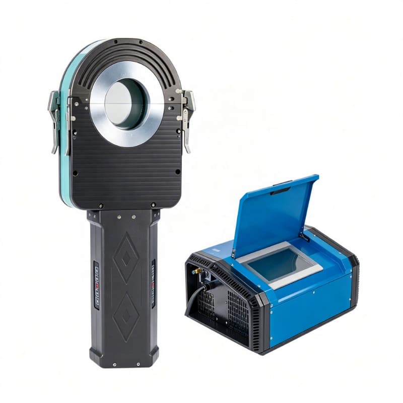
The first selection question is whether the required weld can be made without filler metal. Autogenous welding melts the prepared joint edges together. Its suitability depends on the material, wall thickness, fit-up, required profile, and demonstrated procedure. A conventional closed fusion head is attractive when those conditions are satisfied because it avoids a separate wire-delivery system.
If the joint design calls for added metal, a thicker build-up, or multiple passes, equipment must support the required deposition and torch positioning. An open orbital head with compatible wire feed may be appropriate, but the word “open” does not confirm that a particular system includes those functions.
A small-diameter tube can still have a demanding wall section. Conversely, a relatively large tube may have a thin wall suited to a fusion process. Neither “small tube” nor “large pipe” establishes the correct architecture. Evaluate the heat demand and required penetration with the actual wall and joint preparation.
Fit-up matters particularly when no filler is available to contribute metal to the joint. Gaps, mismatch, ovality, and inconsistent end preparation can alter the weld profile and penetration. Selecting a closed-head orbital system should therefore include a review of how the business will hold preparation within its approved limits across production batches.
Alloy selection affects shielding, heat input, electrode choice, and whether a compatible filler is required. Reactive materials may need broader protection of hot surfaces than a simple diameter-based selection suggests. Dissimilar materials add questions about metallurgy and dilution that cannot be answered by head architecture alone.
Do not transfer an accepted schedule from one alloy or joint family to another merely because the components fit the same clamp. The appropriate welding procedure defines the operating conditions, and its qualification requirements depend on the application. Head capability and procedure suitability must be established together.
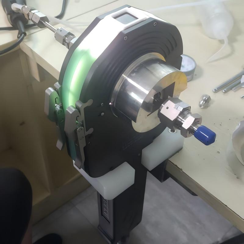
A catalogue diameter range describes which tubes a head may accommodate. It does not establish whether the head can be installed on a crowded assembly. Measure the axial distance from the seam to nearby fittings and the radial space available around the joint. Include the clearance needed to load, clamp, weld, and remove the head.
Compare the complete envelope of the proposed Closed-head Orbital Welding Machine with the actual open-head alternative. A closed design can be compact in one direction and restrictive in another. An open design may have accessible clamping but need space for a wire spool, torch arm, or tracking motion. Architecture alone cannot settle a tight-access case.
The head's metal body is only part of the clearance requirement. Gas lines, cooling hoses, cables, and strain relief need suitable routing. A nearby completed joint, support, or flange can interfere with mounting even when it does not obstruct the weld seam itself. Include these features in the representative trial assembly.
For repeated spool fabrication, assembly order can improve access. Welding one joint before attaching a bulky neighboring component may make an otherwise difficult operation practical. Any change in sequence must remain compatible with the design and production requirements. Access planning is therefore a manufacturing decision as well as a machine-selection decision.
An open head can make the weld zone easier to observe, but observation still requires suitable arc protection. A closed chamber can reduce direct visibility, making sample checks and validated process controls particularly important. Do not assume a camera or remote viewing system is included unless the proposed configuration confirms it.
Both head types need a defined response to interrupted cycles. The work instruction should explain how an interruption is identified, how the affected joint is examined, and who can authorize repair or restart. An accessible weld zone is useful, but it does not itself establish an acceptable repair method.
The selected head must suit the intended production rhythm. A demonstration involving one weld on a cold sample does not establish repeated operation through a shift. Thermal demand accumulates in the head and workpiece, while loading, purge time, and inspection influence the interval between cycles.
Assess the full system: head cooling, power-source duty cycle, cables, consumables, and any wire feeder. Water cooling can support a higher workload in a suitable configuration, but it does not remove operating limits. Specify ambient conditions and the planned schedule when reviewing repeated-production capability.
A fusion cycle can involve fewer deposition variables than a wire-fed process, which can simplify setup for a stable joint family. A wire-fed open arrangement adds variables such as wire speed, delivery position, and coordination with the weld pool. Those functions expand capability but require corresponding setup controls and operator training.
A Closed-head Orbital Welding Machine is therefore not automatically less demanding overall. It may require stringent tube preparation and careful chamber maintenance. An open orbital system can be flexible while needing more attention to local shielding and exposed components. Compare the whole workflow, including the operations that each architecture places upstream of welding.
Worn tooling can affect centering, while contamination or damaged insulation can affect head performance. Electrode condition influences ignition and arc behavior. Cooling and shielding connections also require routine checks. Use the equipment's maintenance instructions and record the interventions that can influence process consistency.
For wire-fed equipment, add the wire path, drive components, and delivery position to the maintenance review. For enclosed equipment, include the chamber condition, seals or interfaces, and clamping components applicable to the design. Maintenance planning should identify service intervals, accessible parts, and the checks required before returning equipment to production.
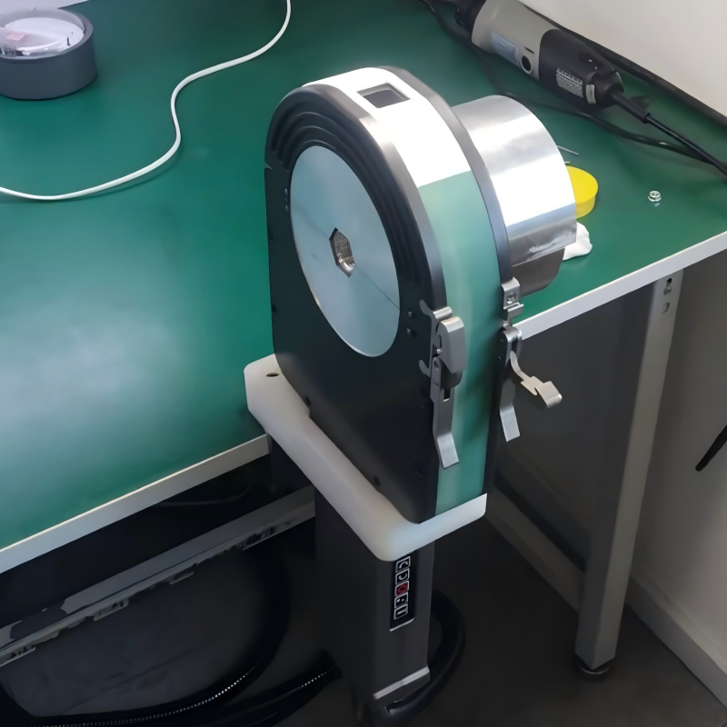
First define the required weld: material, dimensions, preparation, filler requirement, orientation, and acceptance criteria. Then eliminate configurations that cannot execute that procedure. Review the remaining heads for installation clearance and workload. Only after those checks should purchase price and cycle-time comparisons determine the preferred option.
The AS118 Closed Welding Head provides a concrete enclosed-head option for review. It is water-cooled and specified for tube diameters from 38.1 to 114.3 mm with a maximum wall thickness of 3 mm. Those limits define a starting point for application assessment; they do not replace validation of the material, joint preparation, and required weld result.
For a Closed-head Orbital Welding Machine using this head, confirm the compatible power-source arrangement, required clamp tooling, actual assembly clearance, and proposed production cycle. Do not apply the AS118 dimensional range to all closed heads or infer an equivalent open-head range from it.
Buyer question | Evidence to request |
|---|---|
Does the required weld need filler? | Joint drawing and approved process requirements |
Can the head mount and complete travel? | Envelope drawing and representative assembly trial |
Can it sustain the production rhythm? | System ratings and repeated-cycle demonstration |
Does it produce an acceptable internal and external joint? | Representative coupons and the required examination |
Can production control the process? | Program management, maintenance plan, and operator training |
A final comparison should use equivalent accepted joints. A fast fusion demonstration and a multi-pass wire-fed demonstration are not comparable if they address different joint requirements. Measure setup, loading, purging, welding, examination, and changeover on the same production need. This reveals whether shielding control, process flexibility, or handling time is the decisive benefit.
Choose between closed and open orbital heads by the joint's requirements and the complete working envelope. A Closed-head Orbital Welding Machine is a sensible candidate for suitable fusion tube joints with controlled preparation and shielding; an open arrangement may be needed for filler delivery, multiple passes, or specific access conditions. Wuxi Bohan Automation Technology Co., Ltd. manufactures automated welding equipment and offers the AS118 enclosed head. The sound purchasing decision combines verified equipment limits with representative trials, planned maintenance, and the inspection criteria that define an acceptable joint.
Only when the controller, electrical connections, motion interfaces, and required process functions are compatible. Confirm the exact supported combination and any configuration changes.
No universal consumption comparison applies. Torch design, gas timing, joint dimensions, chamber volume, and workplace conditions affect usage. Compare measured consumption for the same accepted application.
That depends on the supply scope and head design. Specify the actual production diameters and confirm which inserts or tooling are included before ordering.
They do not automatically resolve wall mismatch. The preparation and welding procedure must address the actual joint condition, including any permitted transition or dimensional limits.
Compare the complete system, including power source, cooling, tooling, gas supply, and cables. A compact head does not necessarily make the overall equipment package portable.


