


close
Choose Your Site
Global
Social Media
Views: 0 Author: Site Editor Publish Time: 2026-10-01 Origin: Site


A circular tube joint can look simple until the welder must maintain the same penetration around its underside, sides, and top. Restricted access, changing weld positions, and repeated joints make consistency difficult to manage through torch handling alone. An Orbital Welding Machine mechanizes travel around the joint and coordinates the welding cycle. Its value depends on more than producing a neat external bead: buyers must match the equipment to the material, joint geometry, cleanliness requirement, and inspection plan. Understanding those connections helps identify where orbital welding is useful and where another arrangement may be more practical.
Orbital welding moves a welding electrode or torch around a stationary tube, pipe, or circular joint. Orbital TIG systems use programmed current and travel to repeat a defined weld cycle. They are used for clean process tubing, industrial piping, and tube-to-tubesheet joints where controlled welding and repeatability matter.
In an orbital TIG arrangement, an electric arc between a tungsten electrode and the workpiece melts the joint edges. Shielding gas protects the hot weld zone. The weld head carries the electrode around the circumference while the controller coordinates current, motion, and gas timing. Some systems also coordinate filler-wire delivery and cooling. These functions form a process system; the power source alone does not determine the complete application range.
The distinction from a conventional rotating welding station is useful. In orbital welding, the tool travels around a largely stationary workpiece. In a positioner-based arrangement, the component may rotate beneath a torch. Both can automate circumferential welding, but their fixturing, access, and handling requirements differ. A fixed installed pipe favors a travelling head, while a freely movable spool may suit other mechanized arrangements.
Gravity acts differently on the molten pool as the electrode moves around a fixed horizontal tube. The workpiece also becomes warmer as welding progresses. An orbital weld schedule can divide the circumference into sectors and vary the process within those sectors. Pulsed current provides another means of controlling the pool. A single current setting and constant motion are therefore not a universal recipe for every circular joint.
Programmed repeatability is valuable only when the physical starting conditions remain controlled. A stored schedule repeats its commands; it cannot make an oval tube round, remove oil from a joint, or correct every mismatch between adjoining walls. The practical role of an orbital welding system is to reduce variability in a defined operation while preparation and inspection control the remaining variables.
Applications share a need for controlled circular joints, but the reason for automation differs. In clean process tubing, internal surfaces and contamination control can dominate the decision. In thicker industrial piping, filler deposition, access, and repeatable passes may matter more. In heat-exchanger fabrication, the challenge includes repeating tube-to-sheet welds across a dense pattern.
Application | What the weld must support | Equipment question |
|---|---|---|
Semiconductor process tubing | Controlled internal condition and system integrity | Can the head and purge arrangement support the specified cleanliness? |
Pharmaceutical process lines | Inspectable joints and cleanable product-contact surfaces | Can the procedure achieve the required internal profile? |
Food and beverage tubing | Sanitary joint geometry and reliable joining | Are fitting dimensions, preparation, and acceptance criteria defined? |
Chemical and energy piping | Material-specific joint integrity and repeatable passes | Are filler feed, cooling, and access adequate? |
Heat exchangers and condensers | Consistent tube-to-tubesheet attachment | Does a dedicated head fit the tube pitch and joint design? |
A bright external bead does not establish a clean internal weld. For tubing carrying sensitive process fluids or gases, the root condition can influence cleanability and contamination risk. Backing gas protects the inner weld surface when the procedure requires it. Purging must be treated separately from external shielding: an enclosed head protects the outside welding zone but does not automatically displace air throughout the tube interior.
An orbital welding machine can help repeat an accepted process across similar tube joints. It does not sterilize an assembly, validate a cleaning process, or independently demonstrate suitability for a pharmaceutical or semiconductor installation. Those outcomes involve materials, system design, preparation, testing, and the project's acceptance criteria.
Open orbital heads are often considered when filler metal, thicker sections, or multiple passes are involved. Tube-to-tubesheet work instead requires positioning the electrode around the tube opening in relation to the sheet surface. Although both use circular motion, a standard tube butt-welding head should not be assumed to suit a tubesheet joint. Geometry determines the tooling choice before the program is developed.
Industry labels also do not define one common weld specification. Two chemical plants may use different alloys, wall thicknesses, inspection methods, and service conditions. A useful application review begins with a representative drawing and material specification rather than an industry name alone.
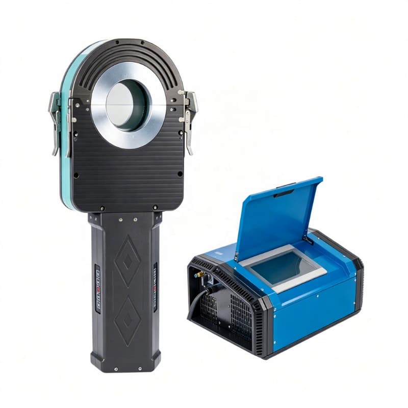
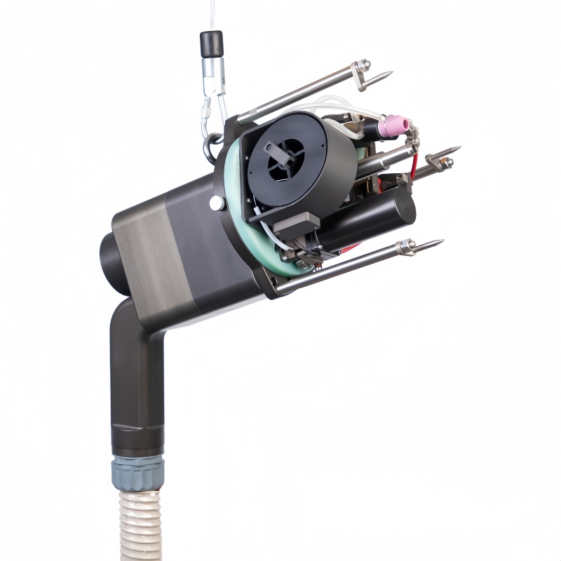
A closed head encloses the external welding zone in a shielding chamber. Conventional closed fusion heads are commonly used for suitable thin-wall joints without filler metal. An open head leaves the torch region accessible and uses local shielding. Compatible configurations can incorporate wire feed and additional motion controls. Neither architecture is universally better; each removes some constraints while introducing others.
Start with the joint design. Autogenous welding joins the parent material without adding filler. It requires a suitable combination of material, wall, fit-up, and procedure. If the design requires deposited metal or multiple passes, the chosen orbital welding equipment must support those functions. Tube diameter alone is an incomplete selection criterion.
Measure radial clearance around the tube and axial space on each side of the seam. Include nearby elbows, valves, supports, and parallel lines. A head may fit around the tube yet lack room to open its clamp or complete its travel. Installation drawings should also account for hoses and cable routing, especially when the joint is already part of a larger assembly.
Head size descriptions cannot replace these checks. A compact enclosed head can work well in some restricted installations, while a particular open-frame design may better fit others. Ask for the actual head envelope and loading sequence. A trial on the real assembly resolves access questions more reliably than comparing tube diameter ranges.
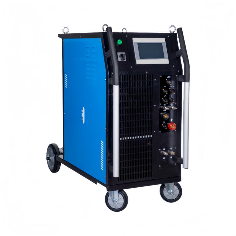
Cooling and workload belong in the same discussion. Occasional welding and repeated production impose different thermal demands on the head, power source, and cables. A water-cooled configuration still has operating limits. Continuous production capability must be assessed for the full system and the actual schedule, rather than inferred from the presence of a cooling tank.
Repeatable orbital welding starts before arc ignition. Cut quality, end squareness, surface condition, alignment, and fit-up affect how the joint melts. A burr or local gap changes the conditions seen by the programmed arc. If operators frequently adjust the schedule to compensate for inconsistent preparation, the process is losing the very repeatability that justified automation.
Preparation requirements should be stated in the work instruction with measurable acceptance criteria. Material identity and dimensions must match the intended procedure. Consumables and gas should be controlled for the application, and electrode condition should be checked. These are manufacturing controls, not optional refinements added after selecting an orbital welding machine.
Develop and assess a weld on a sample that represents the real material, dimensions, fit-up, and orientation. A coupon made under easier conditions may not show what happens beside a bulky fitting or during repeated production. Where the project requires qualification, the responsible welding and inspection personnel should define the necessary examination and documentation.
Inspection should answer the question that matters for service. Visual examination assesses accessible features, but it does not reveal every internal discontinuity. Internal viewing, destructive evaluation, leak testing, or other examination may be required by the design and inspection plan. A recorded weld cycle supports traceability but does not replace examination of the actual joint.
A program identifies the intended settings; a cycle record may document execution. A weld map connects a joint to its location, material, operator, and examination status. These records perform different jobs. Before purchase, establish which records the equipment can produce and which must be maintained through the production system.
When results change, investigate the physical conditions as well as the program. Tube batches, electrode wear, shielding leaks, cooling performance, and preparation can change independently of stored settings. Troubleshooting should preserve the approved process and identify the source of variation instead of repeatedly changing current until the external bead looks acceptable.
An orbital welding machine is a strong candidate when a business repeatedly produces similar circular joints, needs controlled welding in fixed positions, or must manage detailed process records. Its financial value depends on accepted output rather than arc speed alone. Preparation, loading, purging, inspection, and rework all contribute to the completed-joint cycle.
Conversely, widely varying one-off assemblies can consume substantial time in tooling and procedure changes. Poorly controlled incoming parts may require an upstream improvement before welding automation can deliver stable output. An inaccessible joint can remain impractical even when its dimensions fall within a nominal equipment range.
Condition | Decision implication |
|---|---|
Repeated joints with consistent material and fit-up | Evaluate program reuse and reduced process variation. |
Fixed pipe with difficult manual access | Verify head mounting, full travel, and operator visibility. |
Changing designs in very small batches | Compare changeover effort with expected production benefit. |
Frequent fit-up errors | Improve preparation before relying on automation. |
Critical internal surfaces | Include purge control and internal acceptance in the trial. |
A useful purchasing package contains drawings, alloy grades, diameter and wall ranges, joint preparation, access restrictions, expected batch sizes, and inspection requirements. It should also state utilities, the intended work location, and required records. This allows an orbital welding system to be assessed as part of production rather than as an isolated machine.
Run the comparison on representative accepted joints and include changeovers. Record the time to prepare, mount, purge, weld, unload, and inspect. If welding becomes faster but preparation remains the bottleneck, total output may rise only slightly. The correct choice addresses the limiting operation and the acceptance requirement together.
Orbital welding is useful where controlled circular motion and repeatable welding cycles solve a real production or access problem. Select an Orbital Welding Machine by joint design, shielding needs, tooling clearance, and validated weld acceptance rather than by industry label alone. Wuxi Bohan Automation Technology Co., Ltd. manufactures automated welding equipment for pipes, tubesheets, and flanges, including closed and open orbital arrangements. The practical selection remains application-specific: define the joint, verify the complete system, and compare accepted production output. Preparation and inspection turn programmed motion into a dependable manufacturing process.
A power source may serve several compatible heads, but each head has its own diameter, access, cooling, and application limits. Assess the complete combination and any required tooling changes.
No. Suitable joints can be welded autogenously. Other designs require filler metal. That choice follows the joint design, metallurgy, and qualified procedure rather than the automation category.
Possibly, if the head can clamp, align the electrode with the seam, and complete its travel. Check the actual elbow geometry and required straight length with a representative assembly.
A batch change should trigger the checks defined by the production and quality plan. Confirm that the material and resulting weld remain within the approved process before deciding whether any authorized change is needed.
No. Release depends on the project's inspection and acceptance requirements. A log helps connect execution to a weld, while examination establishes whether the joint satisfies the required criteria.


