


close
Choose Your Site
Global
Social Media
Views: 0 Author: Site Editor Publish Time: 2026-10-22 Origin: Site


Hundreds of similar tube openings can create the impression that tubesheet welding is simply a repeated circular weld. In practice, tube projection, hole clearance, sheet thickness, material combinations, and neighboring joints all influence the process. A Tubesheet Automatic Wlding Machine must position the electrode relative to both the tube and the sheet while completing an acceptable joint. Its usefulness depends on the connection design and the complete production sequence, including any expansion and inspection. Defining those conditions before selecting equipment helps avoid a machine that fits the tube diameter but cannot reach or qualify the actual assembly.
Start with the tube-to-tubesheet joint drawing and required weld function. Then check centering, tube pitch, edge access, electrode angle, filler requirements, cooling, and examination. A dedicated orbital head repeats the circular welding path, but the design and validated procedure determine whether the finished connection is acceptable.
A tube-to-tubesheet joint connects a tube end to the surrounding plate. In heat exchangers and related equipment, these repeated connections must perform their specified function under the intended service conditions. Depending on the design, welding may provide sealing, structural contribution, or both. The fabrication team must know what the weld is required to do before developing the program.
A seal weld and a strength weld should not be treated as interchangeable descriptions. The required dimensions, examination, qualification, and relation to any expanded connection follow the engineering design. Selecting a machine from a generic equipment category cannot establish these requirements.
Tube projection determines the electrode's relationship to the tube end and sheet surface. A flush arrangement presents different positioning conditions from a projected tube. Recesses, grooves, sheet cladding, and the surrounding plate geometry may further change the available approach and thermal behavior.
The tubesheet can draw heat away from the joint differently from the thin tube wall. That interaction is one reason a schedule developed for a tube butt joint should not be transferred directly to tube-to-sheet welding. Procedure development must address the actual material combination and connection geometry.
A tubesheet automatic welding machine also requires a suitable means of centering the circular path. Depending on the tooling, tube internal dimensions and accessibility may matter as much as outside diameter. The electrode must follow the intended joint path, not merely a circle near the opening.
Design input | Why it matters | What to establish |
|---|---|---|
Weld function | Defines required joint performance | Seal, strength, or combined design requirement |
Tube position | Changes electrode approach and joint geometry | Projection, flushness, or recess dimensions |
Tube and sheet materials | Influence metallurgy and heat flow | Exact grades, cladding, and filler requirement |
Hole and tube tolerances | Affect centering and fit-up | Permitted clearances and dimensional variation |
Expansion requirement | Affects assembly sequence and joint condition | Design-approved sequence and tooling plan |
Tube-to-tubesheet orbital welding is used in heat exchangers, condensers, boilers, and pressure-vessel fabrication where the connection design calls for welded tube attachment. Repeated patterns create opportunities for program reuse and controlled welding, but the assembly can still contain several joint families requiring different tooling or schedules.
Do not assume that every exchanger requires the same connection method. Tube material, service conditions, design rules, and repair requirements can influence the specified joining arrangement. Equipment should be matched to the approved design rather than used to justify a different joint after purchase.
Orbital tooling can reduce the variation associated with manually following each circular path. The production benefit is strongest when tube placement, surface condition, and fit-up remain consistent across the sheet. If projection varies substantially, the operator may spend time re-setting the electrode at each tube, reducing the value of a stored cycle.
A Tubesheet Automatic Wlding Machine should therefore be evaluated together with tube placement and preparation methods. The practical question is whether the entire assembly process can present a consistent joint to the head, not simply whether the head can complete a circular weld.
New fabrication may offer a clear sheet face before other components are attached. Repair work can involve adjacent finished welds, restricted access, deposits, or limited working space. A head suited to a new production assembly may not be equally practical for repair.
Describe both production and repair needs if the same equipment is expected to serve them. Any removal, repair, or replacement procedure must also satisfy the design and inspection requirements. An automatic cycle does not resolve the engineering questions associated with an existing pressure component.
Tube pitch determines how closely the head, torch, and wire mechanism can approach neighboring tubes. The central region of a regular pattern may be straightforward while edge rows, partition areas, or openings near structural features are more difficult. A drawing review should identify the limiting positions before a trial is planned.
Include the head body, centering device, electrode holder, wire path, and service connections in the clearance assessment. Clearance for the stationary head is insufficient if the torch or feeder encounters an obstruction during rotation. The trial should demonstrate mounting and removal as well as welding travel.
A single tube in an isolated flat plate demonstrates only part of the task. A representative mock-up should reproduce the relevant tube pitch, plate condition, tube projection, and nearby obstructions. Include the joint locations likely to be most difficult, not only the easiest central opening.
If the proposed centering tooling engages the tube interior, confirm that its dimensions and engagement conditions are compatible with the real tube. Material identification, internal condition, and any restrictions on contact or expansion should be considered. Centering must be repeatable without introducing an unacceptable change to the component.
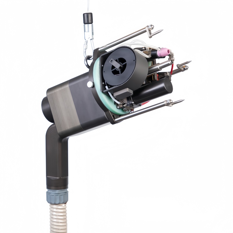
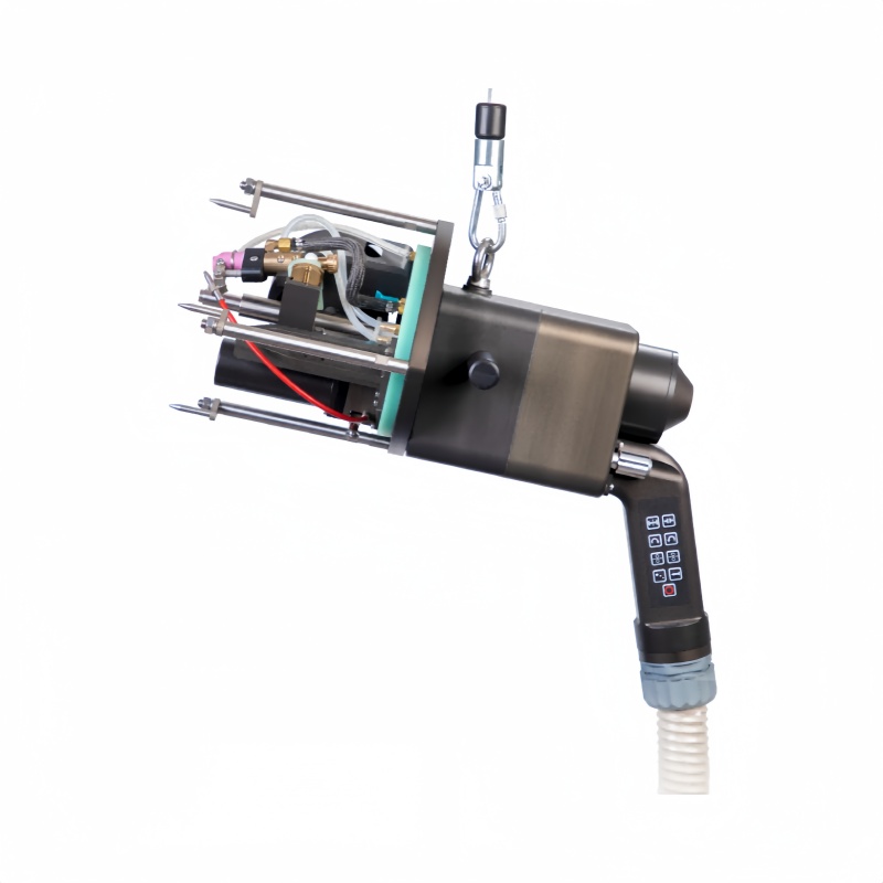
The AT80 Tube Plate Welder is designed for tube-to-tubesheet TIG welding, with an applicable tube-diameter range of 8–80 mm. Its configuration includes water cooling, integrated wire feeding, and an adjustable torch angle for flush and projected tube joints. These features identify relevant process options; the actual tube pattern and joint procedure still require application verification.
For this tubesheet automatic welding equipment, confirm the centering tooling, compatible control arrangement, clearance at limiting locations, and required weld sequence. The diameter range alone does not establish minimum tube pitch, suitability for every recessed design, or unrestricted operation on every material combination.
Preparation controls should specify the condition of the tube ends, hole surfaces, and weld zone. Contamination between a tube and sheet can affect the weld even when the exposed face looks clean. Tube projection and fit-up must be checked against the drawing before an automatic schedule can be expected to repeat successfully.
The interaction between welding and expansion requires particular attention. Expansion can change fit-up and conditions at the interface, while welding can affect the surrounding material. The appropriate order depends on the approved connection design and procedure. Avoid adopting a universal “always expand first” or “always weld first” rule without application review.
Whether a joint needs filler follows its material combination, geometry, required weld dimensions, and qualified procedure. A machine that supports both modes provides options, but availability of a feeder is not a reason to add wire to every joint. Similarly, omitting wire to simplify production is inappropriate if the design requires it.
For wire-fed work, delivery position must remain consistent during the circular motion. Assess the wire path and any risk of interference at neighboring tubes. For more than one pass, establish how electrode position and process settings will change, including any manual adjustment required between passes.
A densely welded sheet can accumulate heat during production. Welding order and intervals can influence distortion and the conditions at later joints. The procedure and fabrication plan should establish any temperature limits, sequence requirements, or checks appropriate to the design.
Cooling the head is separate from controlling the component's thermal condition. Water cooling helps manage equipment temperature, but it does not guarantee acceptable temperatures throughout the tubesheet. Evaluate both equipment workload and workpiece behavior during a repeated-cycle trial.
A Tubesheet Automatic Wlding Machine should be demonstrated over a realistic production sequence. An acceptable first weld does not establish that the last weld in a sustained series will see the same starting conditions. Repeated testing should include the checks required by the application's quality plan.
Inspection must reflect the weld's specified function and the accessibility of the joint. Surface examination, sectioning of qualification samples, leak testing, and other methods answer different questions. The required approach should be established by the responsible design and quality personnel before production.
Where a procedure qualification is required, use samples and examination that represent the real joint. A visually smooth bead does not prove the required fusion, dimensions, or service performance. Program records document the process used, while inspection establishes acceptance of the joint.
Assign identifiers to tube locations so that weld execution, inspection, and any repair can be connected to a physical position. Record the approved program and relevant material or assembly information. This helps contain an issue to the affected production interval instead of leaving an entire sheet without clear status.
If records are needed from the welding controller, confirm the exact available functions. Parameter storage and automatic welding do not necessarily include complete weld-data capture or integration with a quality system. Define the information required and demonstrate how it will be retained.
Production output depends on more than the time spent welding. Positioning, centering, shielding, wire adjustment, inspection, and moving to the next tube all consume time. Track those operations during a representative trial to identify whether tooling, welding, or handling limits throughput.
Production loss | Check before purchase |
|---|---|
Repeated centering adjustments | Tooling fit and tube-placement consistency |
Interference at edge rows | Limiting sheet geometry and full rotating envelope |
Cooling-related pauses | Complete system workload and component temperature plan |
Weld rejection or repair | Representative procedure trial and acceptance criteria |
Unclear joint status | Tube map and record workflow |
A quotation package should include tube and sheet grades, tube dimensions, sheet thickness or cladding, hole tolerances, pitch, projection, joint drawing, expansion plan, required examination, and anticipated production volume. Include utilities and handling constraints. This information makes a tubesheet automatic welding machine proposal assessable before tooling and process choices are finalized.
Successful tube-to-tubesheet orbital welding begins with the connection design and a repeatable assembly condition. Select a Tubesheet Automatic Wlding Machine by centering, clearance, required deposition, workload, and validated acceptance rather than tube diameter alone. Wuxi Bohan Automation Technology Co., Ltd. manufactures automated welding equipment and offers the AT80 tube plate welder with water cooling, wire feeding, and adjustable torch positioning. Representative mock-ups, defined expansion sequence, and joint-level inspection records are essential to judge the complete production method. The goal is consistent accepted connections across the actual tubesheet pattern.
Not necessarily. Pitch, edge geometry, projection, and the complete rotating envelope determine access. Check the most restrictive positions with the proposed tooling.
Only within the validated procedure and setup limits. Projection changes the electrode relationship to the joint and may require different positioning or a separate schedule.
A leak test addresses leakage under its test conditions. It does not establish every structural or fusion requirement; the approved inspection plan determines the required examinations.
It should represent the material and thermal conditions relevant to qualification and application validation. A substantially different plate can give an incomplete picture of the production joint.
No. Head cooling manages equipment temperature. Component distortion and cumulative heating require a fabrication sequence and thermal controls appropriate to the assembly.


