


close
Choose Your Site
Global
Social Media
Views: 0 Author: Site Editor Publish Time: 2026-10-29 Origin: Site


A faster weld does not necessarily mean more completed pipe assemblies per shift. Flange alignment, component loading, preparation, inspection, and repair can consume more time than the arc itself. A Pipe Flange Automatic Welding Machine improves productivity when it makes the required circumferential weld more repeatable and fits the surrounding production workflow. Its value should be measured through accepted assemblies, including changeovers and downtime. That approach helps distinguish a useful automation investment from a machine that finishes the welding step quickly while parts continue to queue elsewhere in the workshop.
Measure accepted joints per available production hour.
Include preparation, loading, alignment, purging, inspection, and changeover.
Validate weld quality and flange geometry on representative assemblies.
Compare complete operating cost and actual usable capacity.
A Pipe Flange Automatic Welding Machine mechanizes the circumferential welding operation and coordinates the relevant process settings. In an orbital arrangement, the welding tool travels around the joint. Other automated production arrangements may rotate the assembly instead. These architectures have different handling and access requirements, so the proposed motion should be established before comparing performance.
The output unit matters. Counting arc cycles can hide rejected joints, incomplete passes, or components awaiting dimensional inspection. Counting accepted assemblies reveals whether the production method actually delivers the required work. The chosen metric should also state whether a joint, flange, or complete spool counts as one unit.
A practical cycle model includes component preparation, loading, alignment, shielding or purging when required, welding, unloading, and examination. Add the batch's share of setup, changeover, planned service, and expected rework. Some activities can overlap in a suitable cell, so measure the actual workflow rather than simply summing every operator action.
Accepted throughput = accepted assemblies ÷ total production time.
Cost per accepted assembly = total relevant production cost ÷ accepted assemblies.
Define the time boundary consistently when comparing manual and automatic work. If one trial starts with prepared parts and the other includes cutting and fit-up, the comparison is misleading. Use the same assembly, preparation quality, inspection criteria, and production boundary.
Measured activity | What automation may improve | What remains to verify |
|---|---|---|
Setup and program selection | Reuse of validated settings | Tooling changes and program-release controls |
Welding | Coordinated motion and process execution | Required passes and acceptable joint result |
Loading and alignment | Repeatable fixturing in a suitable cell | Handling time and flange geometry |
Rework | Potential reduction in process variation | Measured rejection and repair rates |
Inspection and release | More consistent presentation for examination | Actual examination time and record workflow |
Repeated circular joints can benefit from a controlled travel path and a reusable process. Once a suitable schedule is validated, operators can execute it without rebuilding the settings for each equivalent assembly. This can reduce variation between cycles and simplify repeated production of a stable joint family.
Process consistency may also reduce avoidable repair when the incoming parts, setup, and shielding remain controlled. That potential is commercially meaningful because repairs involve more than additional welding: they can consume preparation, handling, inspection, and production-planning time. The benefit must be measured on actual accepted output rather than assumed.
Program recall helps when the same material, dimensions, and joint preparation recur. It can reduce the time spent finding previously established settings. However, the operator still needs to confirm that the physical assembly matches the released program and that the correct tooling is installed.
Group jobs into validated joint families where appropriate. Schedule similar work together to reduce avoidable tooling and parameter changes. The grouping must respect the welding procedure's limits; a similar diameter does not automatically place a different alloy or wall in the same process family.
A Pipe Flange Automatic Welding Machine can coordinate current and travel around the circular seam. Depending on the configuration, it may also control gas timing, cooling, and filler delivery. This supports repetition of the intended process, but it cannot eliminate every disturbance from preparation, material variation, or component temperature.
Stable execution is especially useful when manual torch access varies around the circumference. The actual benefit still depends on whether the head can mount, travel, and be removed efficiently. A joint that takes a long time to fixture may remain a poor productivity candidate despite a repeatable weld cycle.
Automation can change the operator's work from continuous torch manipulation to setup, monitoring, and quality checks. That change may reduce fatigue associated with repetitive positioning and allow a better-organized production rhythm. It does not establish a fixed labor reduction or justify unattended operation.
Operator allocation should follow the equipment instructions, workplace controls, and actual supervision requirement. If the process needs continuous observation, that requirement belongs in the staffing model. Estimate labor savings from measured work content, not from the word “automatic.”
The weld joins components, but the accepted assembly also needs the specified geometry. Flange orientation, perpendicularity, concentricity, and spacing may matter to downstream installation. A consistent weld bead does not compensate for a flange held in the wrong position before welding.
Fixturing should locate the pipe and flange while allowing the required weld access and managing movement appropriately. Include the drawing's dimensional requirements in the trial. Inspect the assembly after welding, because thermal effects can change the geometry from its initial fitted condition.
Heavy or long assemblies can require supports and lifting arrangements that dominate cell time. A compact welding head does not make a large spool easy to load. Review component weight, length, balance, working height, and the available handling equipment when evaluating a Pipe Flange Automatic Welding Machine.
For repeated jobs, a suitable fixture can reduce measuring and repositioning effort. For highly varied work, a flexible fixture may avoid excessive dedicated tooling while requiring more adjustment. The correct approach depends on the product mix and expected batch size, not simply on the machine's welding capability.
Inconsistent cutting, beveling, gaps, or tack condition can create delays and weld variation. If the welding station repeatedly stops to correct incoming parts, increasing its arc speed will not solve the upstream problem. Set preparation acceptance criteria and make the required checks before parts enter the automatic cell.
Separate defects caused by preparation from those caused by welding execution. This makes improvement actions more specific and avoids changing the weld program to accommodate every poorly fitted assembly. Program repeatability works best when the joint presented to it is repeatable.
Check clearance for mounting, electrode travel, wire delivery if used, and removal. Include hoses and cables, nearby fittings, and the actual flange profile. An automatic pipe flange welder should be demonstrated on the most restrictive representative assembly in the intended range.
Where the manufacturing sequence can affect access, consider when to attach neighboring components. Any sequence improvement must remain compatible with the design, inspection access, and production plan. Solving a mounting problem through assembly order can be more effective than buying a larger welding system.
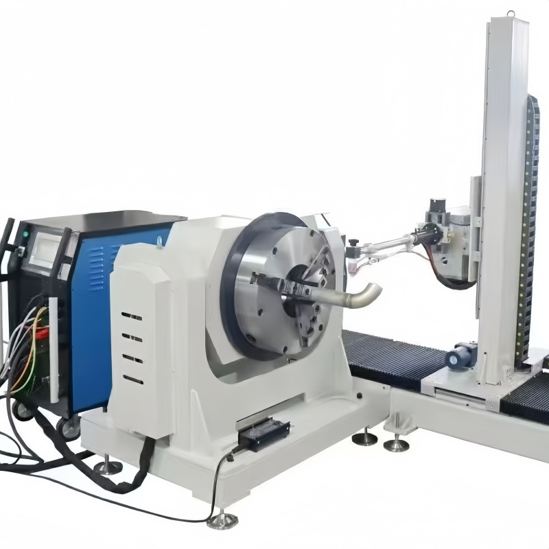
The Automatic Pipe Flange Welder offered by Wuxi Bohan uses an AW400 programmable power source and a flange welding head for circumferential pipe-to-flange welding. The power source has a current range of 5–400 A, and the system uses a 7-inch touchscreen for process interaction. These features support application assessment; they do not establish a universal output rate.
For a proposed Pipe Flange Automatic Welding Machine, confirm the complete supply scope and allowable joint range. Diameter, flange geometry, wall thickness, material, required preparation, and filler needs should be reviewed together. Do not infer a production capacity or acceptance guarantee from current range alone.
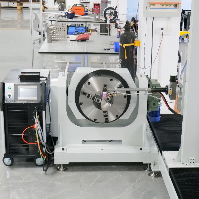
Power-source duty cycle, head cooling, cable ratings, and component temperature affect repeated production. A single successful demonstration does not prove that the system can follow the planned rhythm throughout a batch. Evaluate the full schedule, including required pauses and maintenance.
Utilities and installation conditions also affect usability. Establish electrical supply, gas provision, cooling requirements, working space, and handling arrangements before delivery. Missing infrastructure can prevent a capable machine from reaching its intended production role.
If the procedure needs filler feed, multiple passes, particular electrode motions, or specified records, identify those functions explicitly. Confirm the supported configuration rather than treating all automatic welding systems as equivalent. A purchase specification should connect every required function to a defined joint or production need.
Program storage is useful for recurring assemblies, but program count is rarely the main productivity constraint. Ease of correct selection, revision control, tooling changes, and the time required to validate a new family can matter more. Demonstrate the operator workflow as well as the weld itself.
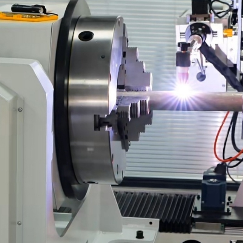
Use representative parts from the intended production mix, including common work and the most demanding access or preparation case. Apply the same acceptance criteria to the baseline and automatic trial. Record accepted output, rejected joints, repair effort, staffing, changeovers, and total occupied time.
Do not compare a highly optimized demonstration with an average manual shift without accounting for the different conditions. A meaningful trial includes normal handling, inspection, and reasonable variation within the allowed preparation limits. This reveals whether the automatic route improves the full process.
Once welding becomes faster or more consistent, preparation or inspection may limit output. Plan how parts will enter and leave the station. Building a queue of unfinished or uninspected spools does not create the same value as increasing released assemblies.
Check whether the downstream operation has capacity for the additional output. If accepted work cannot be released or shipped, the investment case should account for that constraint. Production improvement is strongest when the cell's capacity matches the surrounding process.
A practical annual-benefit estimate combines the verified change in labor, consumables, repair cost, and usable production capacity, then subtracts added maintenance and operating expenses. If the benefit includes more output, establish that the business can use or sell that capacity. Faster welding is not automatically additional revenue.
Simple payback period = installed investment ÷ verified annual net benefit.
Installed investment includes equipment, tooling, utilities, training, commissioning, and required validation. Use consistent assumptions and avoid counting the same saved time both as labor savings and additional production value. Where workload varies, evaluate more than one realistic utilization scenario.
Investment question | Evidence needed |
|---|---|
Will throughput rise? | Accepted assemblies per hour with the same time boundary |
Will repair cost fall? | Comparable rejection rates and total repair effort |
Will staffing change? | Measured operator work and supervision requirements |
Will changeovers erase savings? | Trial timings across the actual production mix |
Can added capacity be used? | Upstream supply, downstream capacity, and expected workload |
Provide drawings, material grades, dimensional ranges, flange types, joint preparation, inspection requirements, typical batches, utilities, and handling constraints when requesting a proposal. This turns a Pipe Flange Automatic Welding Machine comparison into a concrete production review rather than a discussion of unsupported speed claims.
A Pipe Flange Automatic Welding Machine improves productivity when repeatable weld execution reduces the total effort needed to release acceptable assemblies. The strongest gains depend on stable fit-up, suitable handling, manageable changeovers, and enough inspection capacity. Wuxi Bohan Automation Technology Co., Ltd. manufactures automated welding equipment and offers a pipe-flange welding system using programmable process control. Assess it through representative production trials and a cost model based on accepted output. The right investment solves the workshop's limiting operation while preserving the joint quality and geometry required by the project.
Larger recurring batches can spread setup cost over more units, but payback also depends on utilization, accepted quality, handling, and whether the added capacity is useful.
No. The assembly still needs the specified orientation and dimensions. Validate fixturing and inspect the completed geometry as required by the production plan.
Use equivalent parts, preparation, inspection criteria, and time boundaries. Include normal setup and changeover rather than comparing only the fastest arc cycle.
It should remain inside a completed-production comparison when inspection is required for release. Otherwise, apparent output can increase while accepted assemblies remain unchanged.
Improve the preparation and supply workflow or revise the utilization assumption. Unused capacity should not be counted as a realized production benefit.


